华为UPS5000-A-120KTTL,华为120kvaUPS电源技术参数华为UPS5000-A-120KTTL,华为120kvaUPS电源技术参数华为UPS5000-A-120KTTL,华为120kvaUPS电源技术参数华为UPS5000-A-120KTTL,华为120kvaUPS电源技术参数
华为UPS,华为UPS5000-A-120KTTL,华为120KvaUPS

详细参数
| 基本参数 |
| 额定容量 | 120KVA |
|---|
| 额定功率 | 120000W |
|---|
| 额定电压 | AC 380/400/415V |
|---|
| 额定频率 | 50/60Hz |
|---|
| 负载功能 | 8台 |
|---|
| 整机效率 | 系统效率:95.7% |
|---|
| 输入输出参数 |
| 输入配线 | 三相四线+地线 |
|---|
| 输入电压范围 | AC 138-485V |
|---|
| 输入频率范围 | 40-70Hz |
|---|
| 输入谐波 | ≤3% |
|---|
| 输入功因 | 0.99 |
|---|
| 输出电压范围 | AC 380/400/415V±1%V |
|---|
| 输出频率范围 | 在线模式:同步状态下,跟踪旁路输入
电池模式:50/60Hz±0.05%Hz |
|---|
| 输出电压波形 | 100%线性负载下THDv<1% |
|---|
| 输出功因 | 1 |
|---|
| 其它输入参数 | 旁路:
额定输入电压:AC 380/400/415V
输入频率范围:50/60Hz±6Hz |
|---|
| 通信和管理 |
| 接口端口 | 干接点,RS485,SNMP |
|---|
| 过载能力 | 110%负载60min后转旁路,125%负载10min后转旁路,150%负载1min后转旁路 |
|---|
| 电池和运行时间 |
| 电压电流 | DC 360-480V |
|---|
| 电池容量 | 30-40节,电池节数可调,默认32节 |
|---|
| 环境 |
| 工作环境 | 工作温度:0-40℃,工作湿度:0-95%RH(无冷凝) |
|---|
| 存储环境 | -40-70℃ |
|---|
| 操作高度 | ≤1000m,若>1000m,每100m降额1% |
|---|
| 噪音值(dBA) | 58-64dB |
|---|
| 其它参数 |
| 外观尺寸 | 1020×440×850mm |
|---|
| 产品重量 | 240kg |
|---|
| 其它性能 | 内置维修旁路
认证与标准:YD/T,1095-2008,EN/IEC 62040-1,EN/IEC 62040-2,EN/IEC 62040-3,TLC,CE,CB,RoHs,Reach,WEEE等 |
|---|









、


 UPS5000-A-(30kVA-120kVA) 快速指南
1
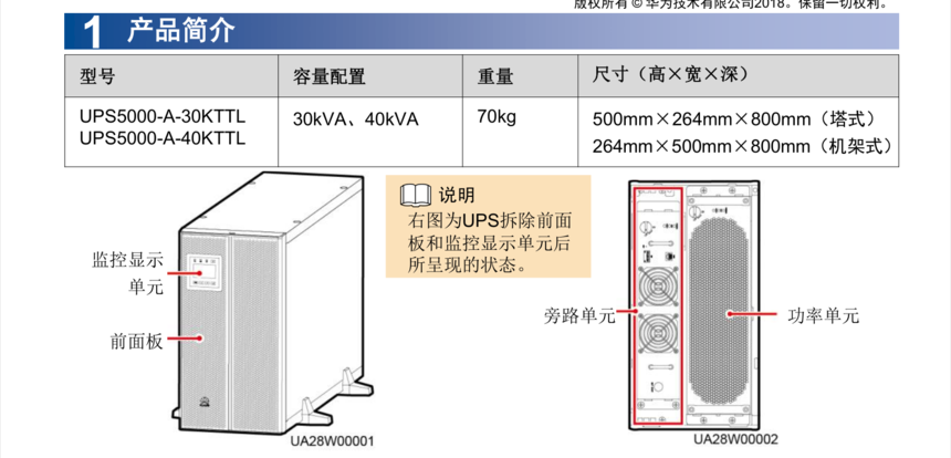
产品简介
型号 容量配置 重量
尺寸(高 × 宽 × 深)
UPS5000-A-30KTTL
UPS5000-A-40KTTL
30kVA、40kVA
70kg
500mm×264mm×800mm(塔式)
264mm×500mm×800mm(机架式)
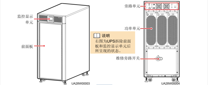
型号 容量配置 重量
尺寸(高 × 宽 × 深)
UPS5000-A-60KTTL
UPS5000-A-80KTTL
60kVA、80kVA
160kg
1020mm×440mm×850mm
UPS5000-A-120KTTL
120kVA
200kg
右图为UPS拆除前面
板和监控显示单元后
所呈现的状态。
监控显示
单元
前面板
旁路单元 功率单元
监控显示
单元
前面板
旁路单元
功率单元
维修旁路开关
右图为UPS拆除前面
板和监控显示单元后
所呈现的状态。
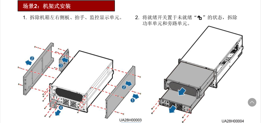
2. 将就绪开关置于未就绪“ ”的状态,拆除
功率单元和旁路单元。
2
安装流程
1. 安装设备前请详细阅读用户手册了解产品信息及安全注意事项。
2. 安装操作设备时,必须使用绝缘工具。
3. UPS必须由华为或其代理商认证的工程师进行安装、调测和维护,否则可能危及人身安全并且导
致设备故障,由此引起的UPS损坏不属保修范围。
2
安装UPS
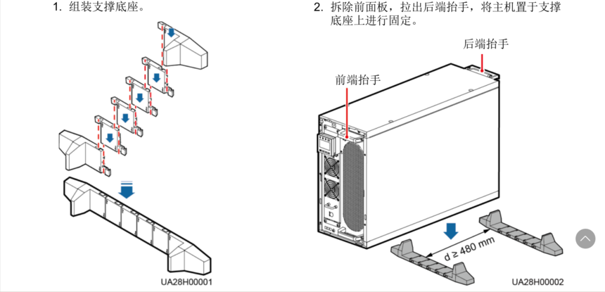
场景1 :塔式安装
1. 组装支撑底座。
场景2 :机架式安装
30kVA/40kVA UPS 2.1
3. 收起后端抬手和安装前面板。
1. 拆除机箱左右侧板、抬手、监控显示单元。
后端抬手
前端抬手
2. 拆除前面板,拉出后端抬手,将主机置于支撑
底座上进行固定。
现用挂耳
原挂耳
3
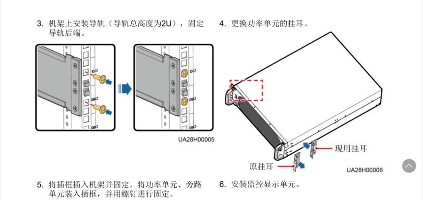
3. 机架上安装导轨(导轨总高度为2U),固定
导轨后端。
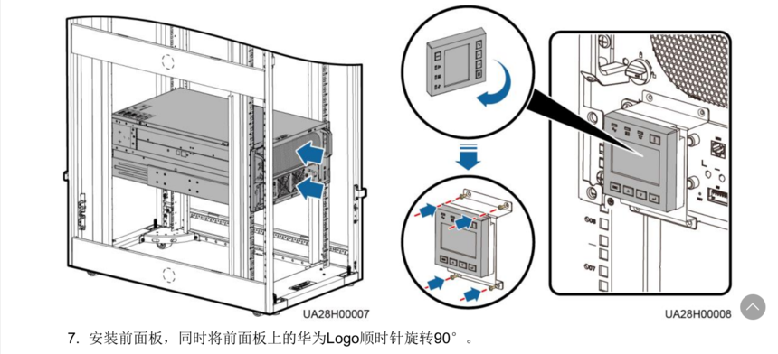
5. 将插框插入机架并固定。将功率单元、旁路
单元装入插框,并用螺钉进行固定。
6. 安装监控显示单元。
7. 安装前面板,同时将前面板上的华为Logo顺时针旋转90°。
4. 更换功率单元的挂耳。
4
安装流程
1. 根据划线模板确定安装孔位,打孔并安装膨胀管。 2. 调节地脚螺栓,先确保地脚螺栓触地,再调
平UPS。
3. 拆除UPS的前盖板。
单位:mm
机柜后
方边缘
L型弯角件固定孔位
前
后
墙体
4. 用L型弯角件将机柜固定在地面。
1. 机架式安装要求对应机架必须符合IEC297标
准,机架深度不小于1100mm,同时机架中导
轨安装深度应大于820mm。
2. UPS较重且需要下走线,建议将UPS安装在机
架的最下方。
场景1 :地面安装
场景2 :机架式安装
60kVA/80kVA/120kVA UPS 2.2
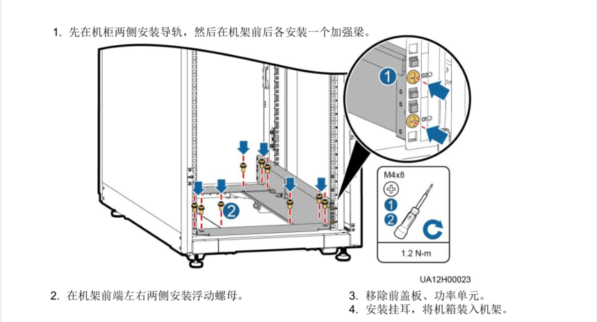
1. 先在机柜两侧安装导轨,然后在机架前后各安装一个加强梁。
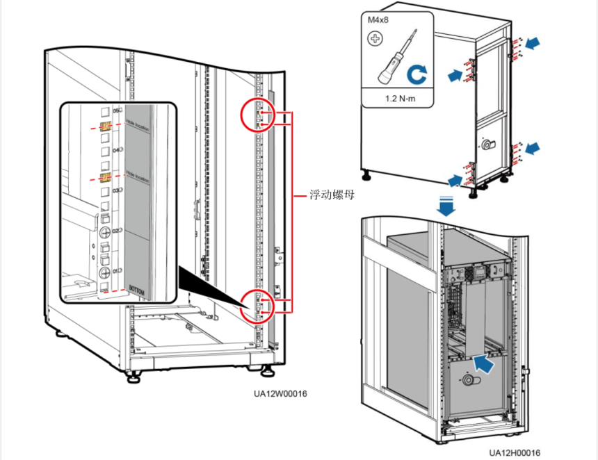
2. 在机架前端左右两侧安装浮动螺母。
浮动螺母
3. 移除前盖板、功率单元。
4. 安装挂耳,将机箱装入机架。
5
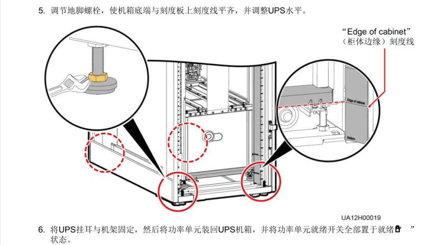
5. 调节地脚螺栓,使机箱底端与刻度板上刻度线平齐,并调整UPS水平。
“Edge of cabinet”
(柜体边缘)刻度线
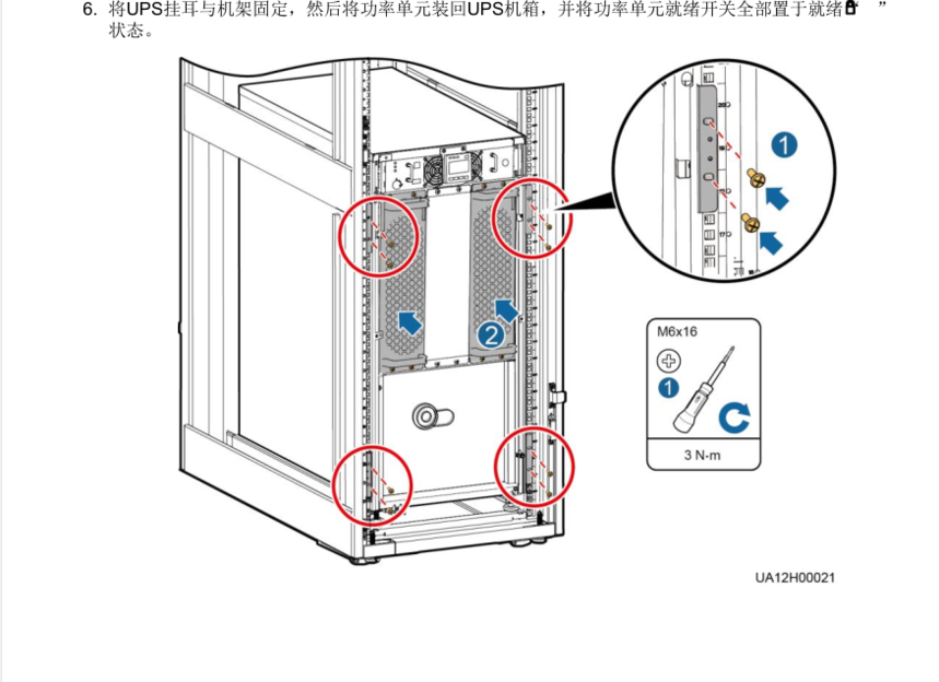
6. 将UPS挂耳与机架固定,然后将功率单元装回UPS机箱,并将功率单元就绪开关全部置于就绪“ ”
状态。
6
7
3
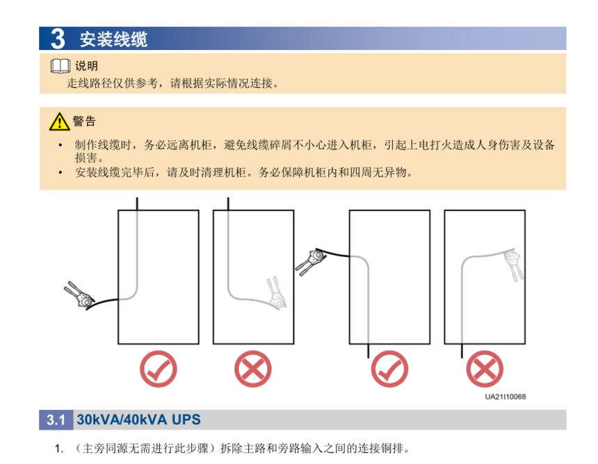
安装线缆
• 制作线缆时,务必远离机柜,避免线缆碎屑不小心进入机柜,引起上电打火造成人身伤害及设备
损害。
• 安装线缆完毕后,请及时清理机柜。务必保障机柜内和四周无异物。
走线路径仅供参考,请根据实际情况连接。
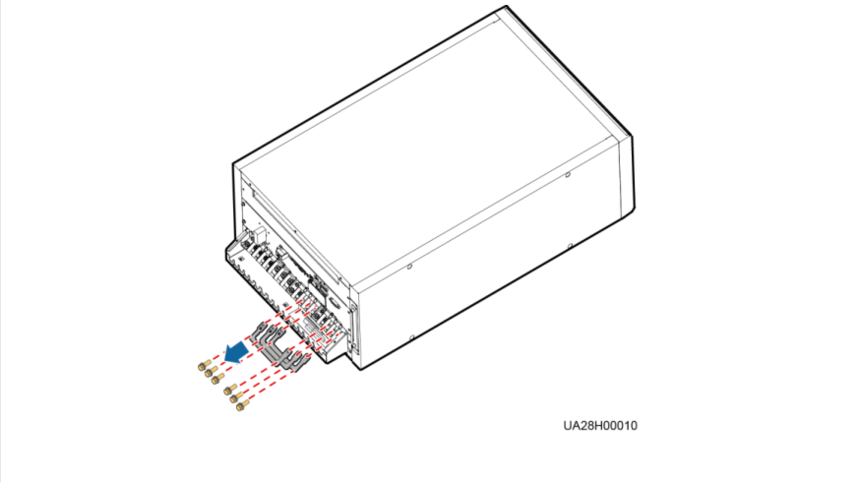
30kVA/40kVA UPS 3.1
1. (主旁同源无需进行此步骤)拆除主路和旁路输入之间的连接铜排。
8
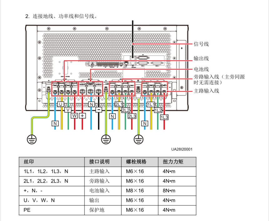
2. 连接地线、功率线和信号线。
从正负电池组中间引出的线即为电池N线。
以40节电池为例,正、负电池组各20节电
池,从正、负电池中间引出的线即为电池
N线。
信号线
电池线
旁路输入线(主旁同源
时无需连接)
主路输入线
图中信号线的数量和颜色仅为示意。
输出线
丝印 接口说明 螺栓规格 扭力力矩
1L1,1L2,1L3,N 主路输入 M6×16 4N•m
2L1,2L2,2L3,N 旁路输入 M6×16 4N•m
+,N,- 电池输入 M8×16 8N•m
U,V,W,N 输出 M6×16 4N•m
PE 保护地 M6×16 4N•m
9
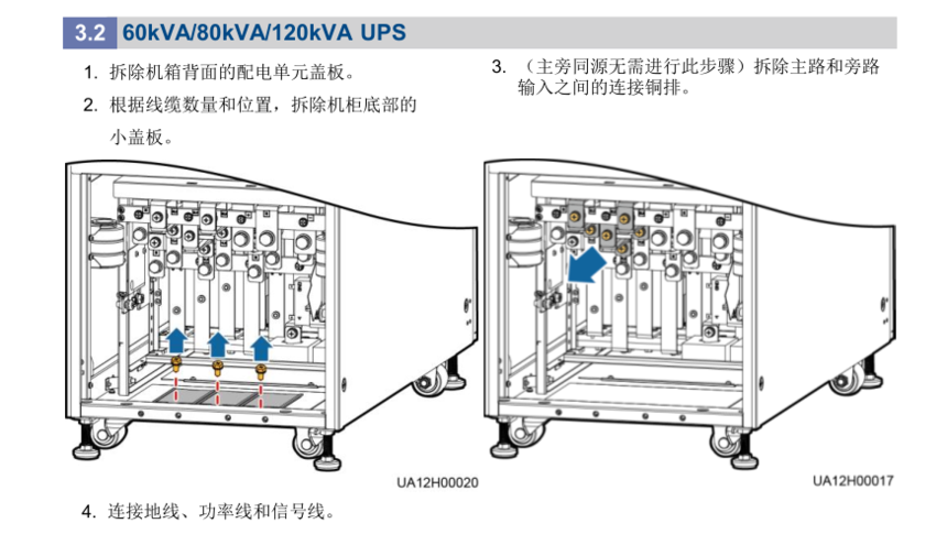
60kVA/80kVA/120kVA UPS 3.2
1. 拆除机箱背面的配电单元盖板。
2. 根据线缆数量和位置,拆除机柜底部的
小盖板。
3. (主旁同源无需进行此步骤)拆除主路和旁路
输入之间的连接铜排。
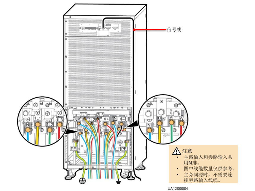
4. 连接地线、功率线和信号线。
• 主路输入和旁路输入共
用N排。
• 图中线缆数量仅供参考。
• 主旁同源时,不需要连
接旁路输入线缆。
信号线
10
从正负电池组中间引出的线即为电池N线。
以40节电池为例,正、负电池组各20节电
池,从正、负电池中间引出的线即为电池
N线。
4
安装后检查
检查机柜顶部、底部、接线铜排、开关和单元后方无异物。
丝印 接口说明 螺栓规格 扭力力矩
1L1,1L2,1L3,N 主路输入 M10×30 35N•m
2L1,2L2,2L3,N 旁路输入 M10×30 35N•m
+,N,- 电池输入 M12×45 55N•m
U,V,W,N 输出 M10×30 35N•m
PE 保护地 M8×20 12N•m
11
UPS 上电 5.1
5
上电开机
1. 上电前,请确认《UPS5000开机服务报告》中检查项均已检查完毕,机柜内外无异物、无积尘、
并机牢固、接线正确规范,确认UPS的所有开关和前级开关均处于断开状态。
2. 测量UPS的输入开关与前级输入开关的电压及频率,电压范围:138V AC~485V AC(线电压),
频率范围:40Hz~70Hz。
3. 上电前,功率单元和旁路单元的就绪开关旋转至“ ”状态。
1. 检查完成后,装回所有盖板。
2. 线缆安装完成并确认无误后,用防火泥填充线缆和机柜之间的缝隙。
3. 如果UPS不急需上电,建议在安装完成后(上电以前)用挡板或塑料袋对UPS进行密封,防止顶
部或内部积灰。
UPS 关键参数设置 5.2
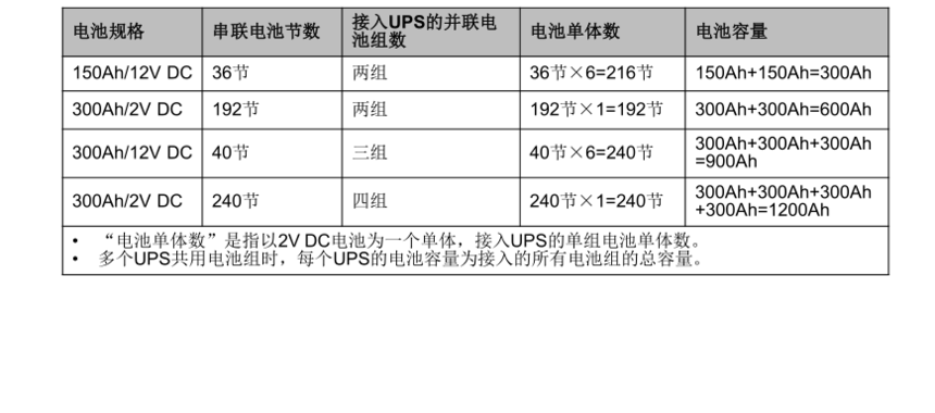
电池规格 串联电池节数
接入UPS 的并联电
池组数
电池单体数 电池容量
150Ah/12V DC 36节 两组 36节×6=216节 150Ah+150Ah=300Ah
300Ah/2V DC 192节 两组 192节×1=192节 300Ah+300Ah=600Ah
300Ah/12V DC 40节 三组 40节×6=240节
300Ah+300Ah+300Ah
=900Ah
300Ah/2V DC 240节 四组 240节×1=240节
300Ah+300Ah+300Ah
+300Ah=1200Ah
• “电池单体数”是指以2V DC电池为一个单体,接入UPS的单组电池单体数。
• 多个UPS共用电池组时,每个UPS的电池容量为接入的所有电池组的总容量。
闭合前级旁路、主路输入开关。
系统上电后,系统开始初始化,同时监控显示单元中显示初始化进度条。
12
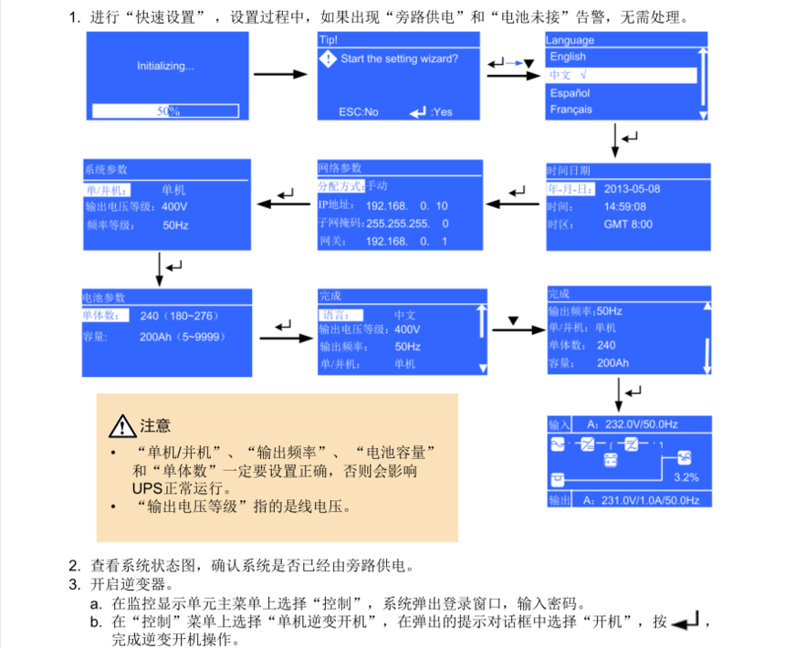
1. 进行“快速设置” ,设置过程中,如果出现“旁路供电”和“电池未接”告警,无需处理。
• “单机/并机”、“输出频率”、 “电池容量”
和“单体数”一定要设置正确,否则会影响
UPS正常运行。
• “输出电压等级”指的是线电压。
2. 查看系统状态图,确认系统是否已经由旁路供电。
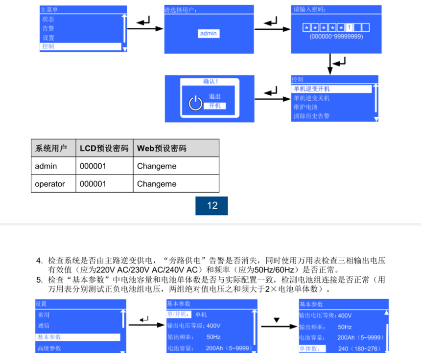
3. 开启逆变器。
a. 在监控显示单元主菜单上选择“控制”,系统弹出登录窗口,输入密码。
b. 在“控制”菜单上选择“单机逆变开机”,在弹出的提示对话框中选择“开机”,按 ,
完成逆变开机操作。
系统用户 LCD 预设密码 Web 预 设密码
admin 000001 Changeme
operator 000001 Changeme
13
4. 检查系统是否由主路逆变供电,“旁路供电”告警是否消失,同时使用万用表检查三相输出电压
有效值(应为220V AC/230V AC/240V AC)和频率(应为50Hz/60Hz)是否正常。
5. 检查“基本参数”中电池容量和电池单体数是否与实际配置一致,检测电池组连接是否正常(用
万用表分别测试正负电池组电压,两组绝对值电压之和须大于2×电池单体数)。
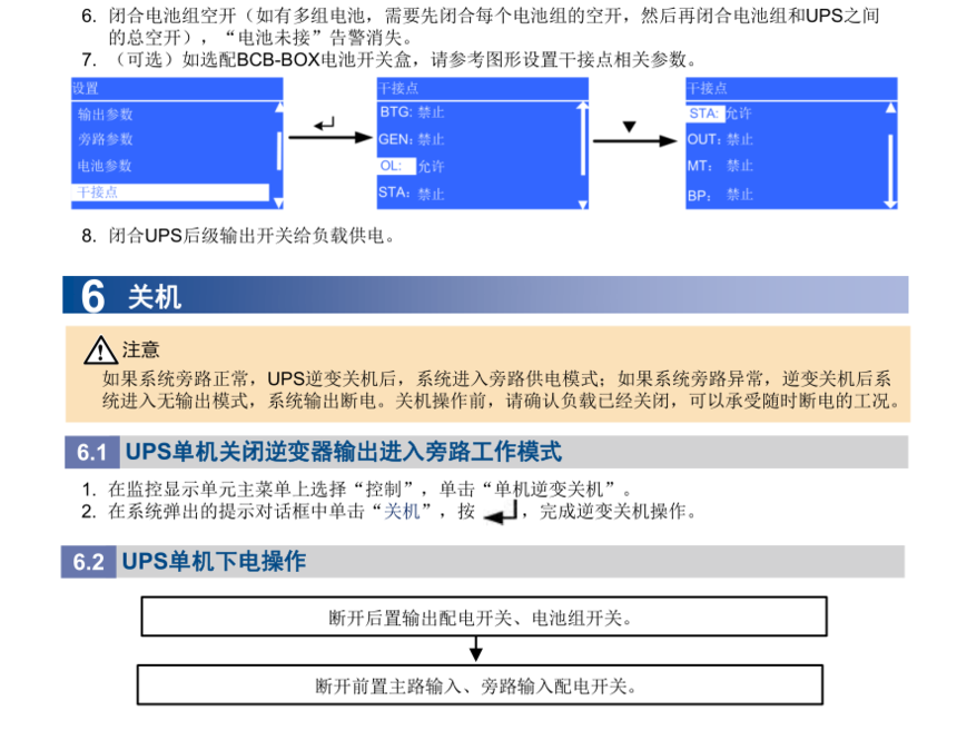
6. 闭合电池组空开(如有多组电池,需要先闭合每个电池组的空开,然后再闭合电池组和UPS之间
的总空开),“电池未接”告警消失。
7. (可选)如选配BCB-BOX电池开关盒,请参考图形设置干接点相关参数。
8. 闭合UPS后级输出开关给负载供电。
UPS 单机下电操作 6.2
断开后置输出配电开关、电池组开关。
断开前置主路输入、旁路输入配电开关。
6
关机
如果系统旁路正常,UPS逆变关机后,系统进入旁路供电模式;如果系统旁路异常,逆变关机后系
统进入无输出模式,系统输出断电。关机操作前,请确认负载已经关闭,可以承受随时断电的工况。
1. 在监控显示单元主菜单上选择“控制”,单击“单机逆变关机”。
2. 在系统弹出的提示对话框中单击“关机”,按 ,完成逆变关机操作。
UPS 单机关闭逆变器输出进入旁路工作模式 6.1
14
7
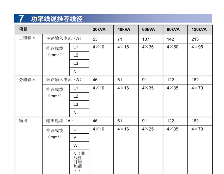
功率线缆推荐线径
项目 30kVA 40kVA 60kVA 80kVA 120kVA
主路输入
主路输入电流(A)
53 71 107 142 213
推荐线缆
(mm 2 )
L1 4×10 4×16 4×35 4×50 4×95
L2
L3
N
旁路输入 旁路输入电流(A) 46 61 91 122 182
推荐线缆
(mm 2 )
L1 4×10 4×16 4×35 4×35 4×70
L2
L3
N
输出 输出电流(A) 46 61 91 122 182
推荐线缆
(mm 2 )
U 4×10 4×16 4×25 4×35 4×70
V
W
N(非
线性
时增
加截
面)
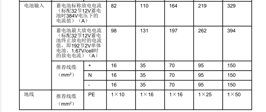
电池输入 蓄电池标称放电电流
(标配32节12V蓄电
池时384V电压下的
电流值)(A)
82 110 164 219 329
蓄电池最大放电电流
(标配32节12V蓄电
池终止放电时的电流
值,即192节2V单体
电池、1.67V/cell时
的放电电流)(A)
98 131 197 262 394
推荐线缆
(mm 2 )
+ 16 35 70 95 150
N 16 35 70 95 150
- 16 35 70 95 150
地线
推荐线缆
(mm 2 )
PE 1×10 1×16 1×16 1×25 1×50
UPS5000-A- (30kVA-120kVA) quick guide
One
Product introduction
Model capacity allocation weight
Dimensions (high * width * Deep)
UPS5000-A-30KTTL
UPS5000-A-40KTTL
30kVA, 40kVA
70kg
500mm * 264mm * 800mm (tower type)
264mm * 500mm * 800mm (rack type)
Model capacity allocation weight
Dimensions (high * width * Deep)
UPS5000-A-60KTTL
UPS5000-A-80KTTL
60kVA, 80kVA
160kg
1020mm * 440mm * 850mm
UPS5000-A-120KTTL
120kVA
200kg
The right picture is UPS.
After board and monitoring display unit
The state of presentation.
Monitoring display
unit
front panel
Bypass unit power unit
Monitoring display
unit
front panel
Bypass unit
Power unit
Maintenance Bypass Switch
The right picture is UPS.
After board and monitoring display unit
The state of presentation.
2. put the ready switch in the "ready" state.
Power unit and bypass unit.
Two
Installation process
1.
before installing the equipment, please read the user manual carefully
to understand the product information and safety precautions.
2. insulation tools must be used when installing operating equipment.
3.
UPS must be installed, tested and maintained by engineers certified by
Huawei or its agents, otherwise it may endanger personal safety and
conduct
Equipment failure, resulting in UPS damage is not covered by the warranty.
Two
Install UPS
Scene 1: tower installation
1. assemble the support base.
Scene 2: rack mount
30kVA/40kVA UPS 2.1
3. retract the rear end lift and install the front panel.
1. dismantle the left and right sides of the chassis, lift up the hand, and monitor the display unit.
Backend lifting
Front end lift
2. remove the front panel, pull the rear end lift, and place the mainframe in support.
Fixed on the base.
Hanging ears
Original ear
Three
3. guide rail installed on the rack (the total height of the guide is 2U).
Guide rear end.
5. insert the frame into the frame and fix it. Power unit and bypass
The unit is loaded into the frame and fixed with screws.
6. install monitoring display unit.
7. install the front panel and rotate the HUAWEI Logo clockwise 90 degrees on the front panel.
4. replace the hanger of the power unit.
Four
Installation process
1.
confirm the installation hole according to the scribing template,
perforate and install the expansion pipe. 2. adjust the anchor bolts,
first ensure that the anchor bolts touch the ground, and then adjust
them.
Flat UPS.
3. remove the front cover of UPS.
Unit: mm
Back of the cabinet
Square edge
Fixed hole position for type L bending member
Front
after
wall
4. fix the cabinet on the ground with the L corner member.
1. rack mounting requirements corresponding to the rack must comply with the IEC297 standard.
The depth of the rack is not less than 1100mm, while the rack is guided.
Rail installation depth should be greater than 820mm.
2. UPS is heavier and needs to go offline. It is recommended to install UPS on the machine.
The bottom of the shelf.
Scene 1: ground installation
Scene 2: rack mount
60kVA/80kVA/120kVA UPS 2.2
1. first install guide rail on both sides of the cabinet, then install a reinforcing beam around the frame.
2. install floating nut on the front and left sides of the rack.
Floating nut
3. remove front cover and power unit.
4. install the hanging ear and install the chassis into the rack.
Five
5. adjusting the anchor bolts, leveling the bottom of the chassis with the scale plate and adjusting the UPS level.
"Edge of cabinet"
Calibration line (cabinet edge)
6.
Fix the UPS lug with the rack, then load the power unit into the UPS
chassis, and put all the power unit ready switches in place.
State.
Six
Seven
Three
Installation of cable
*
When making cables, be sure to stay away from the cabinet and avoid
accidental entry of cable debris into the cabinet, causing personal
injury and equipment caused by electric lighting
Damage.
Please
clean the cabinet in time after installation of cable. We must ensure
that there are no foreign bodies in and around the cabinets.
The route is for reference only. Please connect according to the actual situation.
30kVA/40kVA UPS 3.1
1. (main side homology does not need to take this step) to remove the connection between main road and bypass input.
Eight
2. connect ground wire, power line and signal line.
The line drawn from the positive and negative battery pack is the battery N line.
Take 40 batteries as an example, the positive and negative battery pack has 20 power saving.
The line drawn from the positive and negative batteries is the battery.
N line.
The signal line
Battery line
Bypass input line (main side homology)
No connection needed
Main road input line
The number and color of the signal lines are only schematic.
Output line
Screen printing interface specification for bolt specification torque torque
1L1, 1L2, 1L3, N main channel input M6 * 16 4N M
2L1, 2L2, 2L3, N bypass input M6 * 16 4N M
+, N, - battery input M8 * 16 8N - M
U, V, W, N output M6 * 16 4N M
PE protected land M6 * 16 4N M
Nine
60kVA/80kVA/120kVA UPS 3.2
1. dismantle the distribution panel cover on the back of the chassis.
2. remove the bottom of the cabinet according to the number and location of cables.
Small cover plate.
3. (main side homology does not need to take this step) to demolish main road and bypass.
Input the copper bar between the connections.
4. connect ground wire, power line and signal line.
Main path input and bypass input
Row with N.
The number of cables in the picture is for reference only.
When the main side is homologous, there is no need to connect.
Bypass the input cable.
The signal line
Ten
The line drawn from the positive and negative battery pack is the battery N line.
Take 40 batteries as an example, the positive and negative battery pack has 20 power saving.
The line drawn from the positive and negative batteries is the battery.
N line.
Four
After installation inspection
Check the top, bottom of the cabinet, copper bar, switch and unit without foreign objects.
Screen printing interface specification for bolt specification torque torque
1L1, 1L2, 1L3, N main channel input M10 * 30 35N M
2L1, 2L2, 2L3, N bypass input M10 * 30 35N M
+, N, - battery input M12 * 45 55N - M
U, V, W, N output M10 * 30 35N M
PE protected land M8 * 20 12N M
Eleven
UPS power on 5.1
Five
Power off
1. before the power up, please confirm the check items in the UPS5000 boot service report.
华为-48v通信高频直流开关电源
华为通信电源,华为开关电源,华为-48v开关电源,华为高频开关电源,华为直流电源
华为通信电源,华为电源官网,华为高频开关电源,华为-48v开关电源,华为开关电源模块,华为网络机柜,华为服务器机柜,华为室外一体化机柜,华为OLT电源,华为直流电源,华为开关电源,华为综合柜,华为UPS,UPS5000-E,UPS2000-A,UPS2000-G,UPS8000-D,UPS5000-A,华为TP48200,华为TP48300,华为TP48600